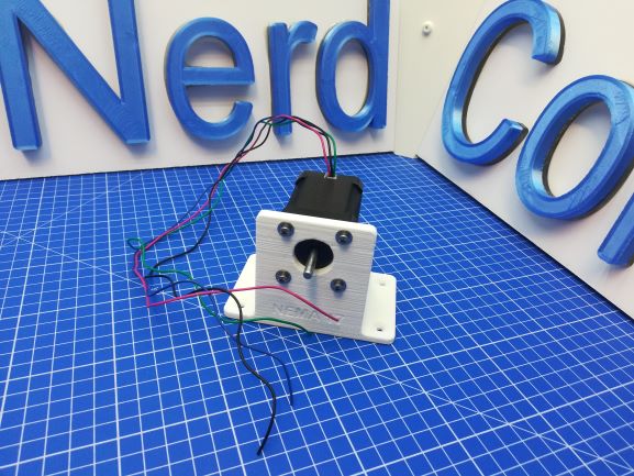
This is an extremely light, yet stable stepper motor stand. Perfect for testing stepper motors! There is enough space to the floor or to a table top. The holder is easy to print and even has mounting holes. It can be mounted with a screw clamp or any another clamp. You can find the STL file for the stepper stand Nema 17 at the end of the post! I also included a STL file for Nema 14
I used the following Solid Works features to create the stepper stand Nema 17: Extruded Boss/Base, Extruded Cut, Hole Wizard, Fillet, Champfer
This might also be interesting for you: SolidWorks design for a LED magnet board
What was the motivation?
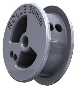
I wanted a stepper motor holder for tests that can be mounted either directly (with screws) or indirectly (e.g. screw clamp) on a table or plate. This stepper motor holder should also be designed to be light for transport but also stable for continuous use. It was essential to include a high ground clearance as I wanted to attach a drum to the motor axis. Of course, there must be a mounting hole for the motor flange and holes for screwing the motor to the holder.
The holes are specified by the NEMA17 standard. Since I mostly deal with the NEMA17 motor sizes and the motors are cheap. I spent hours searching the internet for a suitable stand. Unfortunately I couldn’t find any stepper stand Nema 17 on the internet that met my requirements. So I decided to build a stepper motor stand myself!
How to design a Stepper stand Nema 17 in SolidWorks?
Since all the dimensions and requirements for the stand are known, you can directly start with the construction. I decided right from the start to produce the holder on the 3D printer. I always use SolidWorks to archive this.
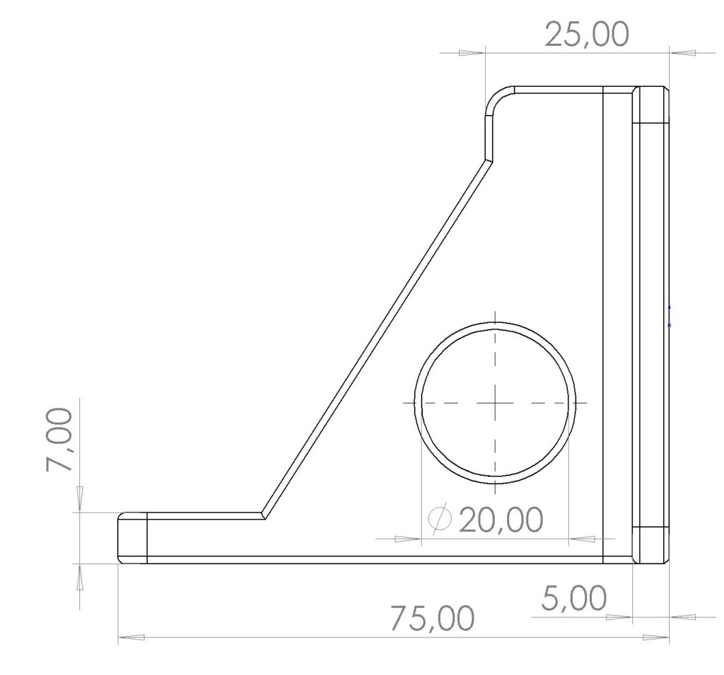
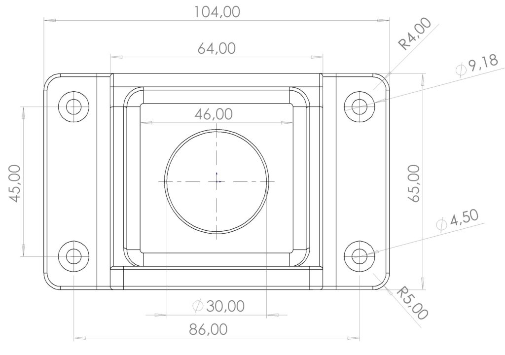
The base plate is first drawn in order to obtain a reference surface and to initiate a so-called tower construction. It should be noted that the base plate must be sufficiently long and wide to ensure high stability. The length of the base plate creates space for fastening screws or for screw clamps that can be attached to the side. The screw clamp(s) attached in the middle would leave no space for the drum. The width results from the average length of the stepper motors, the motor should not protrude too much at the rear. The height of the base plate should be sufficiently dimensioned at 5 mm and prevents warping during 3D printing. There is a large hole in the middle of the base plate. It saves weight and gives stability, as the fiber flow becomes stronger when printing into a round shape.
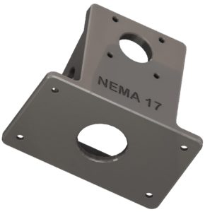
Now for the so-called tower: I’ll make it rectangular in the middle of the base plate and across its entire width. The wall thickness is empirical and the four sides are advantageous against twisting and also better than an objectionable construction with support ribs. Then I realize the flange bore together with the screw holes with the cut feature and use the dimensions of the NEMA17 standard. The side cut makes it easy to bring the holder into shape and makes it easier to mount the motor later. The rounding that is then attached is used for optics and rigidity.
The drilling wizard can be used to create the holes and countersinks for the fastening screws. The advantage of the drilling assistant is the selection of standard threads or countersinks for countersunk head screws or flat countersinks. This feature saves tedious searches in tables for screws or core holes for threads. The assistant does it all! Finally, create an STL file for CURA and use it in the 3D printer. I had a lot of fun again and I hope you guys too!




One thought on “Solid Works: Stepper Stand Nema 17”